


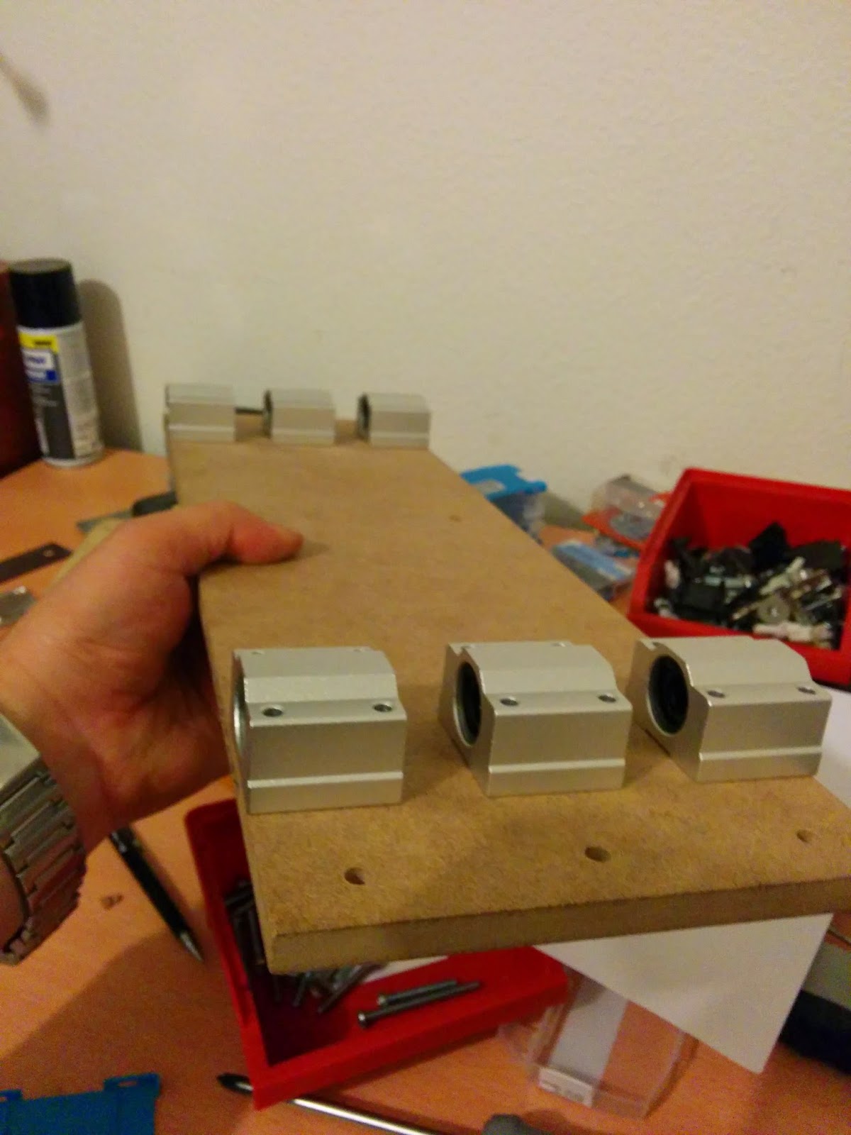
The most important thing is to drill the holes at the EXACT location, otherwise your steel rod will lock into the bearings and will not move or move with a lot of friction. Before tightening the bolts for the linear bearings, we need to use the steel rod in place to align the linear bearings. This will also reduce the risk of locking. Below you can see the final MDF structure with all 6 bearings attached to it.

The whole MDF structure is attached to the aluminum extrusions as shown below.

The MDF must be a perfect cut along the sides, they must be exact width of gantry and the sides must be parallel. As I have changed the plans:), I needed to disassemble the base frame and drill new holes for the new rail locations. To mount the steel rod I used 12mm shaft supports as seen below. One of the face plates in the base frame has also a hole with diameter of 13mm. This hole is used to slide the steel rod into its place. This hole will not be seen as it will be the back plate.


Images below show how I inserted the steel rod into place and mount the gantry.


Below you can find several pictures that show the details from different angles. Also, I have just placed the spindle motor to its final location to visualize how will it look like.


Here also you can find the video of rail moving as expected.
No comments:
Post a Comment