
As I mentioned in earlier posts I needed to support the gantry from sides so that it would be stiff enough for the bending forces that may occur. I used aluminum sheet and cut the rectangles based on my updated design. To mount this plate, I did not use the fancy aluminum extrusion mounting stuff. Instead, I drilled all the way through the extrusion and used a M5 screw and nut to keep the plate in place.


Also for the back side of the gantry, I needed something for the support and motor mount. So again used aluminum plate. Below you can see the final assembly. The problem here was to decide the places for the holes so that nothing will interfere with each other.


I started one by one mounting the risers and the shaft supports for the steel rods of X axis. Without mounting the back plate and aluminum extrusion, I did a test fit with the X Axis base plate. It looked good to me and I decided to continue although I had 0.63 mm error on the right side. While I was drilling I forgot to tap a guide mark on the aluminum and drill wanted to move 0.63mm down. Below are pictures from different angles.


Again, one step back:) In order to drill the motor mount and belt drive holes, I needed to disassemble the back plate. Actually, the test fitting was very helpful as I re-measured the distances for where I have to drill. Below picture with 4 holes is for motor mount and picture with 2 holes is for pillow block bearing that holds the belt drive pulley.


I started again mounting the things together. First I mounted the plate, then the back aluminum extrusion.


Time to mount the motor... There is a bevel on top of the motor for standard mount brackets. To compensate this bevel, I used simply 4 washers between the plate and the motor. Please note that the washer height must be exactly the height of bevel and it should not be a large washer.


Using a drill would help you as you get tired mounting/unmounting things:)


Now time to mount the billow block bearing for the X axis belt drive.


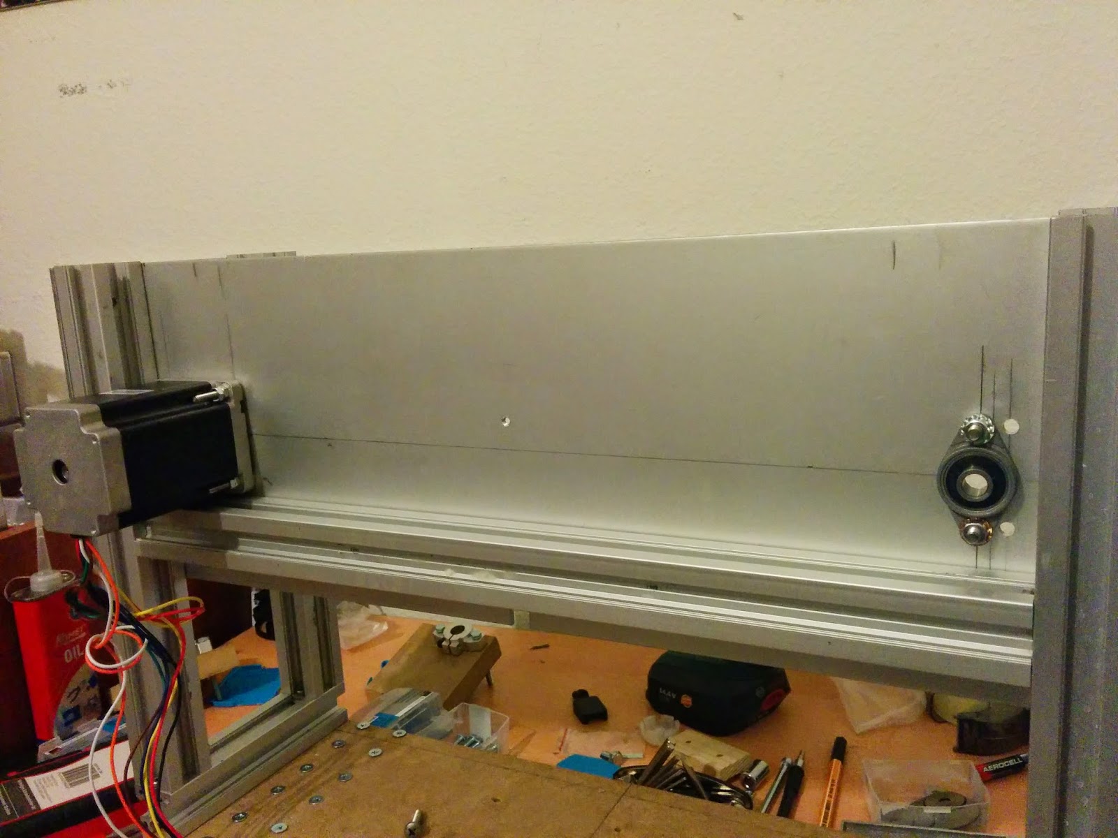
The pillow bearing I used has an inner hole diameter of 8mms. I have used just ordinary aluminum rod as it is not that important to use steel rod. I have already got steel hardened 8mm rod but i used aluminum. You may say aluminum is not strong enough but the length I used is 40mm and only 10mm is out of bearing which is used to hold pulley. Also the nature of the movement is that we have a rotation and the force applied by the belt tension is applied to all the sides of the aluminum rod during rotation. So I HOPE IT WONT BEND:)


So final assembly looks like below with and without pulley...


So now the fun part:) building the Z Axis carriage. I started with the exact same size of MDF I used for Y axis carriage. This helped me a lot during aligning the linear bearings to Y axis. I needed to drill the holes to mount the Z axis motor on the X axis plate. I marked them and drilled with the drill press. Here again I needed washers to compensate the motor bevel. For the motor shaft hole I used 10mm drill bit so it would move easily with 2 mm clearance as the motor shaft has 8mm diameter.


Now, I needed to drill the holes for the pillow block bearing for the pulley of Z Axis. I have such a great design that I used the shaft support holes to mount pillow bearing:) No need for extra holes.


Time to mount the motor.


Time to build the pulley shaft for Z axis. Again 8mm aluminum rod...


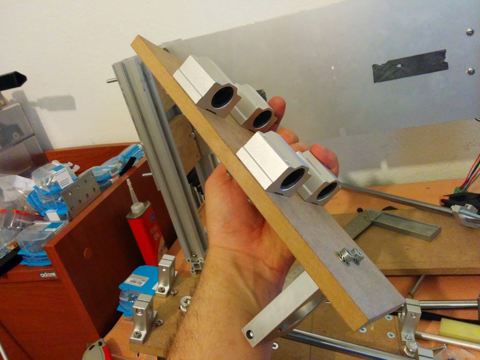
To visualize how linear bearings fit, below are a couple of pictures before the real mounting.


Now, from MDF I marked the holes for linear bearings for Z axis carriage and drilled them with drill press.


I counter sunk the holes so screw heads will be flush with the surface. Now, mounting the linear bearings to Z carriage.


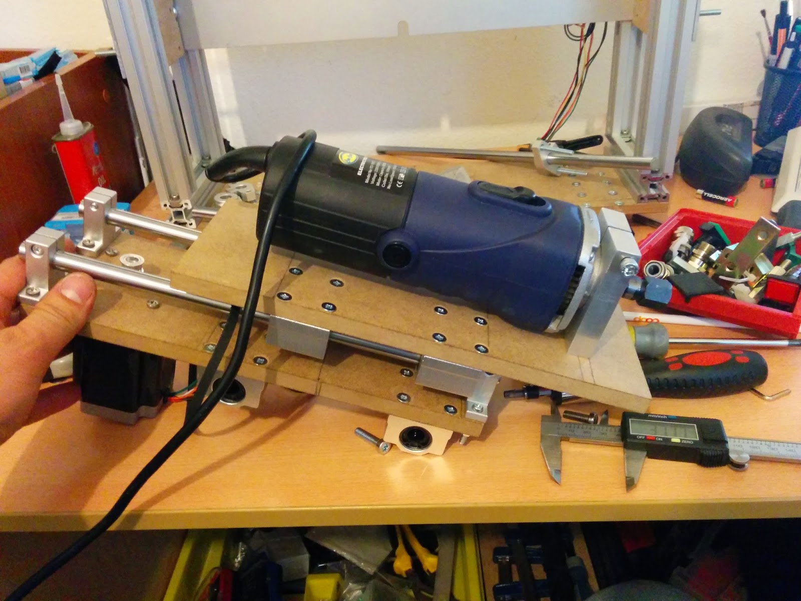
I mounted the spindle mount as well. See below.

Now time to assemble Z carriage with X axis. The most tricky part is to bind the belt to Z carriage. For this I need exact space between the X and Z carriages. I will show this in the next post.


And here is the final assembly.

Hope you are enjoying the posts. Make a comment if you would like to see something in detail. See you next time....
Bonjour Mer, puisque vous êtes un spécialiste. vous demander de me montrer le meilleur modèle à Kit CNC avec ce que j'ai besoin de dispositifs
ReplyDeletePour fabrication un table rotor de décision pour la gravure sur bois ou de plâtre et Merci
Email. Djafrielhadj30@gmail.com dessinateur
Bonjour,
DeleteOk. Je vais créer un poste et vous informer quand il est prêt ici. Je vais poster les informations ici dans le blog pour tout le monde de le voir. Si vous parlez anglais ou allemand, je peux être plus utile. Mon français est très mauvais
In English:
Hello,
Ok. I will create a post and inform you when it is ready here. I will post the information here in the blog for everybody to see it. If you speak English or German, I can be more helpful. My French is very bad.
I can't seem to connect my belt so the z axis can move up and down without the belt coming out of one side like a bubble if you understand me . When z aside moves up the belt like has a bubble and when Sadie goes down belt slips thanks
ReplyDeleteHi,
DeleteMost probably you have an alignment issue in the bearings. The axis of the bearings may not be parallel so the belt is slipping. Also it may be because of belt tension. it may be either to tight or to loose. The bearings actually work like a crown pulley if the belt is pulled out of the bearing. Could you please send me a picture of your z-axis setup so I can comment on better?